In Part III of our Quick Intro Series (don’t forget Part I and Part II), we discussed getting the SRX up quickly as a basic router. We did, unfortunately, skip over some pretty important details along the way such as interfaces and things like that. In this fourth part of our series, we’ll look at some of the other details of the SRX Series Gateway and introduce some additional terms one must know.
One of the things I mentioned in Part III when setting up the SRX for first use was the setting for fe-0/0/0. Well, what is fe-0/0/0? Let’s take a look at the ports on front of the machine:
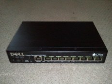
The first ethernet-looking slot you see is the console slot that you can use a console cable to connect with and communicate with the device using Hyper Terminal. The actual ethernet slots are the ones out to the right of the console slot and they are labeled 00 – 07. For the Juniper SRX, the slots – interfaces as they will be called from now on – are represented by a naming scheme that describes them in detail. The following breaks it down:
fe-0/0/0 – media type
fe-0/0/0 – Flexible PIC concentrator number
fe-0/0/0 – Physical Interface Card number
fe-0/0/0 – Port number
Obviously, for a device as small as the SRX100, we will never have to worry about the Flexible PIC number or the Physical Interface Card number ever getting above zero. On the larger datacenter devices which may have rows and rows of interfaces, I’m pretty sure things get interesting real fast. Let’s take a quick look at media types – the prefix of the interface name:
fe – Fast Ethernet 10/100
ge – Gigabit Ethernet 10/100/1000
xe – 10 Gigabit Ethernet
tl – T1
The media type tells what kind of interface it is. The SRX100 is fe only which means all interfaces are 10/100 only. The SRX210 has two Gigabit Ethernet interfaces (ge) and the rest are Ethernet (fe). Obviously, you’ll need to go to the higher end models to get the higher end Interfaces. I’ll not be covering all that here since my concentration is mostly going to be on the SRX100 and SRX210 for the branch office (I do not work at a large school/corporation etc. that will utilize one of the bigger models – that and I could only afford an SRX100 for my house.  )
)
Each physical interface can have many logical interfaces applied to it. A Logical Interface is an entity with a protocol or suite of protocols, and perhaps a network address, assigned to it. The Logical Interface is known as a Unit. A Unit contains protocol definition and each physical interface can have up to 16,000 Units applied to it. Each Unit has a Family. A Family is a protocol configuration (Family of protocols). Here are some examples of Families:
inet – IPv4 network
inet6 – IPv6 network
ethernet-switching – switching protocol if you want this physical interface to just be used in a switch
PPPoE – Protocol used by DSL providers
Here are some examples of Logical Interface configurations:
- First Physical Interface set with a static IP address
fe-0/0/0 {
           unit 0 {
                 family inet {
                           address 192.168.30.50/24
                  }
         }
}
This would be a typical configuration used to set this Interface up to work with a static IP address assigned by your ISP.
fe-0/0/2 {
           unit 0 {
                 family ethernet-switching {
                           members vlan-trust;
                  }
         }
}
In this example, we have set another interface up as a switching port on a Virtual LAN called “trust”. You will see the words “trust” and “untrust” used quite a bit in the SRX documentation. While you may name a VLAN or security zone anything you wish, “trust” and “untrust” are typically used to represent your local area network and Internet connection, respectively.
We now know that each port, or slot, on the front of the SRX is called an Interface. We now also know that we can assign Logical Interfaces to Physical Interfaces. Logical Interfaces include protocol families such as IP settings for different media or to merely have the port act as a switch. For example, you could assign the necessary protocols, such as a static IP or DHCP if you don’t have a static IP, to your fe-0/0/0 for connection to your ISP and then have fe-0/0/1 – fe-0/0/7 set up as switching ports so you can plug your computers into those interfaces. Below is how this typical configuration would look in the command line interface of the SRX:

Notice that, in the above example, fe-0/0/1 – fe0/0/7 are all members of a vlan called trust. You could assign each interface to a different vlan (trust1, trust2, trust3, etc.) with DHCP as a service for each one thereby placing every device connected to those interfaces on its own subnet. Believe me, the fun don’t stop there! I’ll have examples in future posts.
In our next blog post, we will cover the concept of Zones in the SRX which will end our Quick Intro series to the Juniper SRX. Further blog posts will cover more in-depth topics.
James


